
Globe valves
Product description
Globe valves are linear shut-off and control valves designed for complete flow shut-off (on-off), as well as precise control of fluid flow in a pipeline. Unlike gate valves, globe valves are specifically designed for throttling and flow control, thanks to the linear movement of the disc toward the seat and favorable control characteristics.
They are characterized by good control capability, reliable sealing and stable operation at high pressures and temperatures, making them a standard solution in systems with steam, condensate, superheated water and process fluids. Because the flow direction changes inside the valve body, globe valves have higher hydraulic resistance compared to gate and ball valves, but allow significantly more precise flow control.

Applications

District heating and cooling systems

Gas plants

Energy and thermal power plants

Chemical and petrochemical plants
Basic technical specifications
DN15 (1/2") – DN600 (24") and larger on request
PN16 (Class 150) – PN420 (Class 2500)
-29°C to +600°C (depending on material and design)
ASTM A216 WCB, A217 WC6, A351 CF8/CF8M, 1.0619 and equivalent materials
13Cr, Stellite (STL), SS304, SS316, WC6 and equivalent materials
SS420, A182 F6a, A182 F304/F316 and equivalent materials
flanged, welded (BW/SW) or threaded connections, made per EN, DIN, ANSI/API and GOST standards
handwheel, pneumatic, electric or hydraulic actuators
EN 13709, BS 1873, ASME B16.34, API 623 and other relevant standards
Globe valve construction designs

By body shape
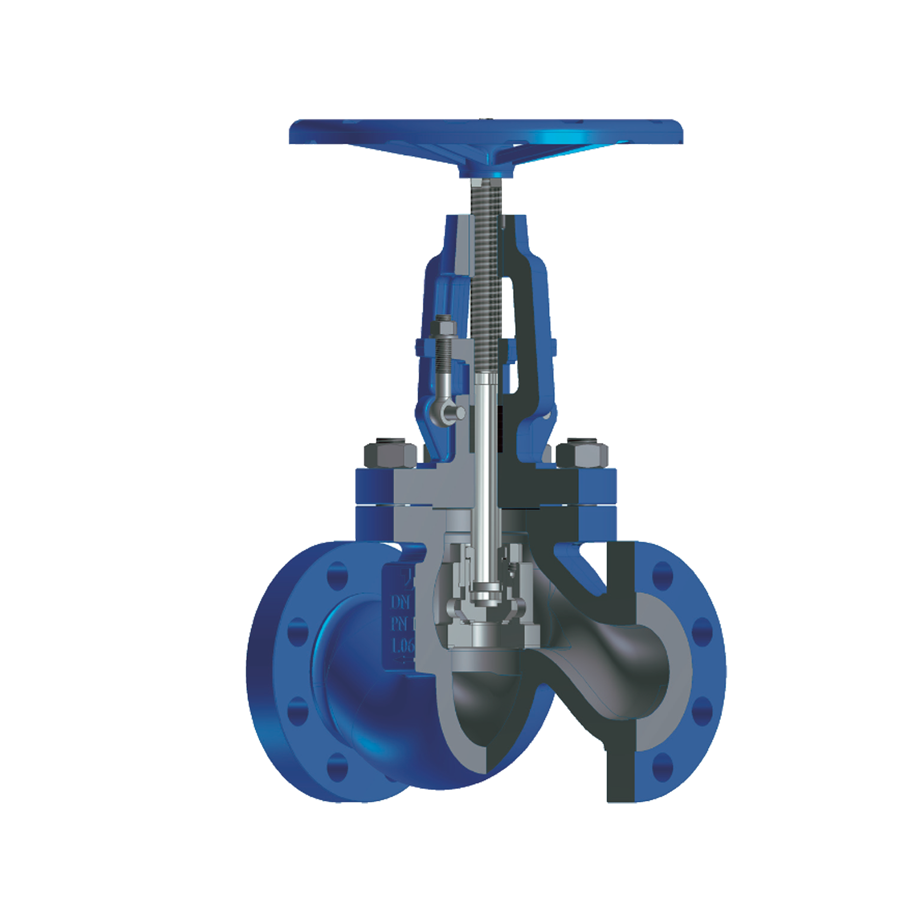
Standard (T-pattern / Z-body)
The most common globe valve design, in which the fluid changes flow direction inside the valve body in a "Z" shape, achieving very good control characteristics and reliable sealing, with a higher pressure drop compared to other valve types.
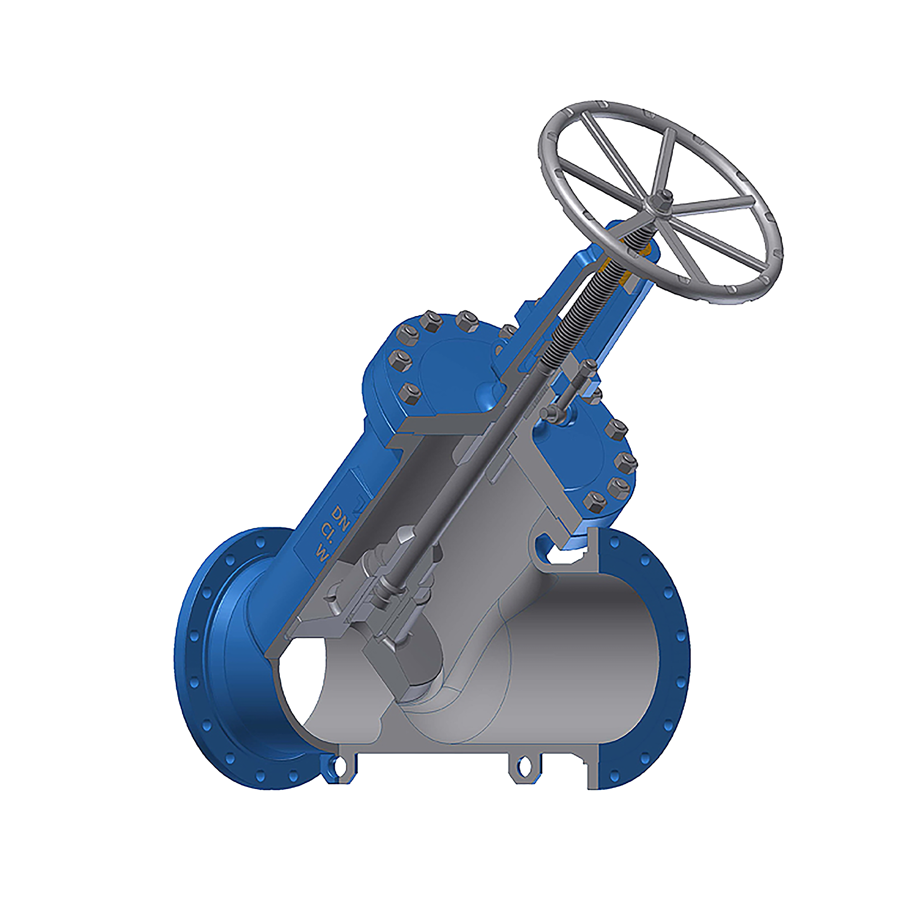
Y-pattern globe valve
A design with an angled seat and stem position that provides significantly lower hydraulic resistance and pressure drop compared to the standard globe valve. Particularly suitable for steam pipelines and high-temperature, high-pressure systems.
Angle (Control) design
A design in which the valve simultaneously changes the flow direction by 90°, reducing the need for additional pipeline elbows. Often used in drainage, bypass and control lines.

By disc design
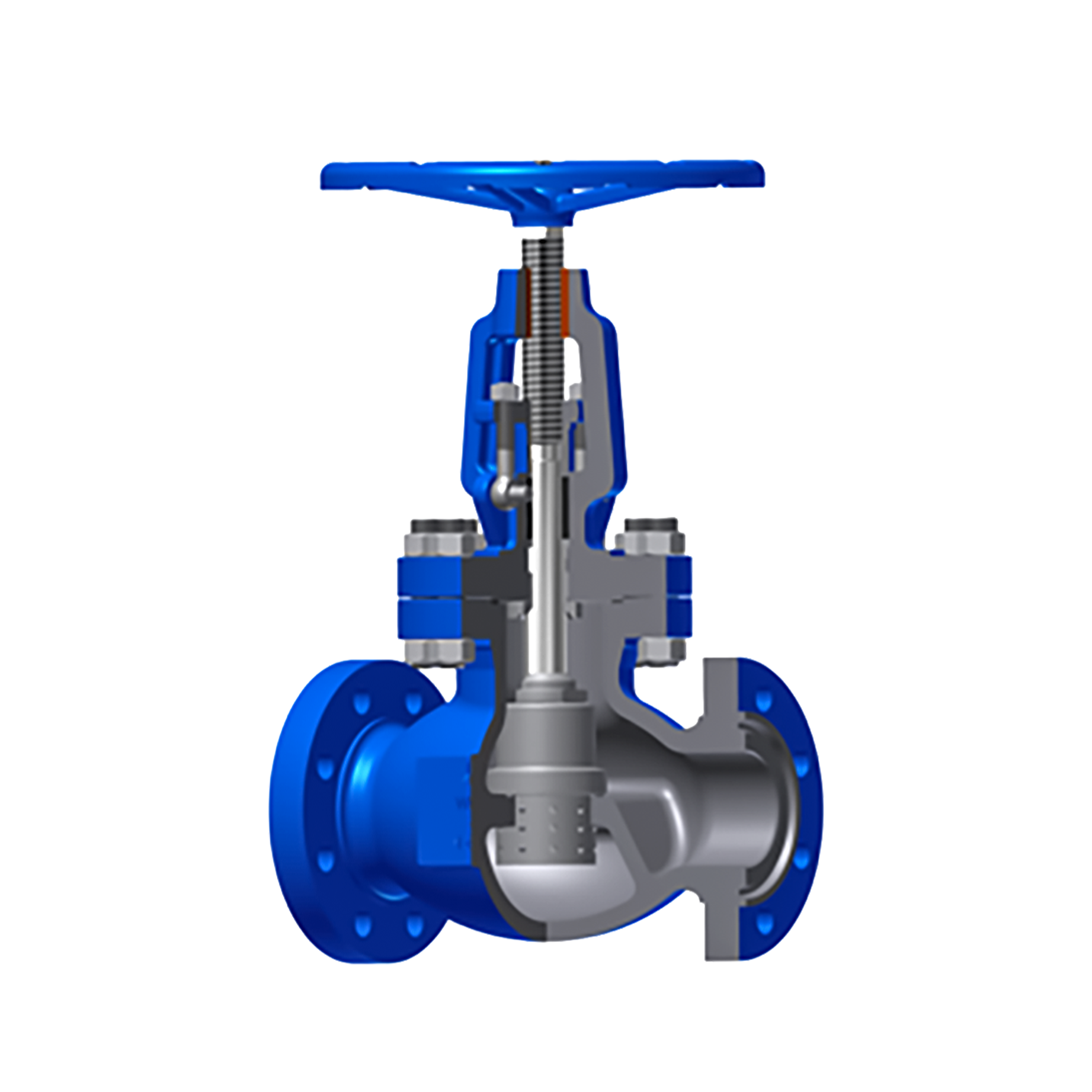
Plug disc (control disc)
A conical-shaped disc intended for precise flow control and throttling. Most commonly used in process and energy systems.
Composition disc
A disc with additional soft sealing material that provides better sealing at lower pressures and temperatures.
Parabolic disc
A special disc design engineered for more stable and precise flow control under variable operating conditions.

By stem and bonnet design
Bolted Bonnet (BB)
The most common globe valve construction, in which the body and bonnet are joined with bolted connections and a gasket between the mating surfaces, providing simple maintenance and reliable operation across a wide range of operating conditions.
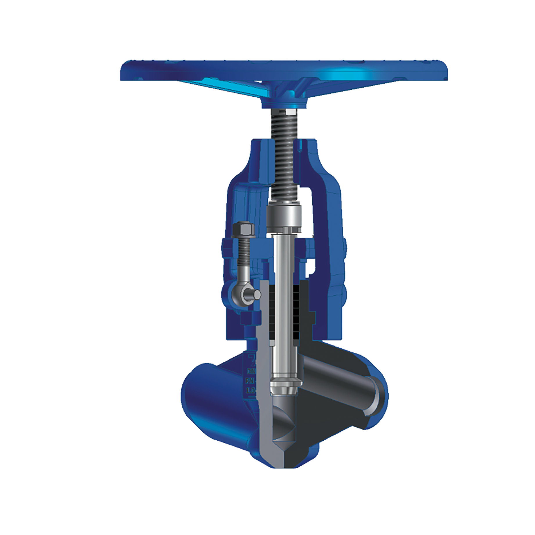
Pressure Seal Bonnet (PSB)
A design intended for high pressures and temperatures, in which the internal fluid pressure further improves the tightness of the joint between the body and the bonnet.
OS&Y (Outside Screw and Yoke)
A rising-stem design in which the thread is located outside the fluid zone, allowing visual indication of the valve's position and reduced thread wear.
Standards and certification
The valves are manufactured in accordance with relevant European standards for energy and industrial equipment.
Manufacturing and quality control includes the following certificates and standards:
- ISO 9001
- ISO 14001
- PED (2014/68/EU) – module H
- EN 13709
- BS 1873
- API 623
- ASME B16.34
- EN 12266-1
- API 598 (testing)
- ATEX 2014/34/EU
- Fire Safe (API 6FA / API 607 / ISO 10497)
Valves delivered by manufacturer on previous projects


Project support and valve selection
The choice of an appropriate globe valve depends on the system's purpose, the type of medium, working pressure, temperature, pipeline nominal diameter, required level of control, and the allowable pressure drop in the installation. Unlike gate valves, which are used exclusively for fully opening or closing flow, globe valves are chosen when more precise flow control, throttling, or stable operation under variable operating conditions is required.
The expert team at Contex Energy provides technical support to designers, contractors and industrial users in selecting the optimal globe valve design for a specific system. Based on the project documentation and operating parameters, it is possible to define the appropriate body shape, disc type, body and sealing surface materials, connection type, operating method and required delivery standards.

Contact us for more information

Schedule a free consultation here
Related services
Contex Energy also provides the following services:


Frequently asked questions
Globe valves are used for complete flow shut-off, as well as for controlling fluid flow in pipeline systems. They are particularly suitable for systems requiring throttling, flow control, or stable operation under variable conditions. Often used in steam pipelines, condensate systems, superheated-water systems and process industry.
Gate valves are used exclusively for fully opening or closing flow, while globe valves are also intended for control. In globe valves, the disc moves linearly toward the seat, allowing more precise flow control. Because of this, globe valves are used where control matters more than minimal hydraulic resistance.
Yes, globe valves are specifically designed for flow control and throttling. Their construction allows stable flow adjustment under various operating conditions. They are therefore often used in energy, thermal power and process systems.
Globe valves have a higher pressure drop because the fluid changes direction inside the valve body. This design increases hydraulic resistance compared to gate or ball valves. On the other hand, it allows significantly more precise flow control.
Globe valves are most commonly used in district heating and cooling systems, steam pipelines, condensate systems, thermal power plants and process industry. They are also suitable for systems with superheated water, thermal oils and technological fluids. Used wherever reliable shut-off and precise control are needed.
T-pattern, or Z-body, is the most common globe valve design and provides good control, but with a higher pressure drop. The Y-pattern design has lower hydraulic resistance and is suitable for high temperatures and pressures. The angle globe valve changes flow direction by 90 degrees and is often used on drainage, bypass and control lines.
The plug disc has a conical shape and is used for precise flow control. The composition disc has additional soft sealing material and is suitable for better sealing at lower pressures and temperatures. The parabolic disc is used when more stable control is needed under variable operating conditions.
Pressure Seal Bonnet is a bonnet design intended for high-pressure, high-temperature systems. In this design, the internal fluid pressure further improves the sealing between the body and the bonnet. It is therefore often used in demanding energy and thermal power plants.
Yes, globe valves can be fitted with pneumatic, electric or hydraulic actuators. Automation enables remote control and more precise regulation of flow, pressure or temperature. Used in systems requiring greater process control and integration with plant control systems.
The appropriate globe valve is chosen based on the medium, pressure, temperature, nominal diameter, required control level and allowable pressure drop. It's also important to define the body shape, disc type, materials, pipeline connection and operating method. The final choice should align with the project documentation and the system's technical requirements.